
circuit diagram
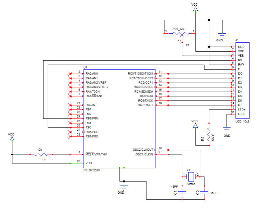
These codes are according PIC 18f series controller and c18 compiler. You can use these codes for any other controller with few modifications. I seated configuration bits in IDE so you can write configuration codes with these codes or configure in IDE. It’s your choice. I am using 20Mhz external crystal and 10ms delay function according 20Mhz frequency.
CODES
#include<p18f2520.h>
#define RS_PIN PORTBbits.RB3 /* PORT for LCD RS_Pin */
#define E_PIN PORTBbits.RB5 /* PORT for LCD E_Pin */
#define DATA_PORT PORTC
#define TRIS_DATA_PORT TRISC
//————————————————————————–
void LCD_Init(void);
void Str_LCD( const rom char *buffer);
void Chr_LCD(char data);
void clrscr(void);
void Move_Corsor( char Line, char Pos);
//————————————————————————–
void Start_Display(void);
void Refresh_Display(void);
void Time_10ms(void);
void main()
{
TRISB=0x00;
TRISC=0x00;
T0CON=0x06;
LCD_Init();
while(1)
{
Start_Display();
Refresh_Display();
}
}
//————————————————————————-
void Time_10ms()
{
TMR0H=0xFE;
TMR0L=0x7A;
T0CONbits.TMR0ON=1;
while(INTCONbits.TMR0IF==0);
T0CONbits.TMR0ON=0;
INTCONbits.TMR0IF=0;
}
void LCD_Init()
{
RS_PIN=0; //LCD instructions (RS) pin no. 4
Chr_LCD(0x38); //LCD 8 Bit Data
Chr_LCD(0x01); //LCD clear
Chr_LCD(0x0C); //LCD diplay on cursor not blinking
Chr_LCD(0x80); //LCD cursor Pos. begain
RS_PIN=1; //LCD DATA (RS) pin no. 4
}
void Str_LCD( const rom char *buffer)
{
while(*buffer) // Write data to LCD up to null
{
Chr_LCD(*buffer); // Write character to LCD
buffer++; // Increment buffer
}
return;
}
void Chr_LCD(char data)
{
PORTC=data;
E_PIN=1;
Time_10ms();
Time_10ms();
E_PIN=0;
Time_10ms();
Time_10ms();
}
void clrscr(void)
{
RS_PIN=0;
Chr_LCD(0x01);
Chr_LCD(0x80);
RS_PIN=1;
}
void Move_Corsor( char Line, char Pos)
{
RS_PIN=0;
if(Line==1)Chr_LCD(0x80);
if(Line==2)Chr_LCD(0xC0);
while(Pos!=0)
{
Chr_LCD(0x14);
Pos–;
}
RS_PIN=1;
}
void Start_Display()
{
Str_LCD(“Starting Display”);
}
void Refresh_Display()
{
clrscr();
Str_LCD(“Updating”);
}
